Meyer Expansion Valve Gear
This weekend I’ve had a good run in the workshop and almost completed the valve drive gear for the Meyer expansion valve. As per previous posts, I don’t intend building the Meyer valve itself, until the whole engine is complete and working well. Since you can’t see inside the valve chest, then no one will know anyway…
 To create the drive from the second eccentric, I decided to stick fairly close to the Stuart plan, I didn’t want to change the “style” of the design. The second valve rod is 1/2 an inch higher than the primary valve rod for the slide valve itself.
So, I simply added 1/4 inch to all the linkages and to the length of the second valve rod.
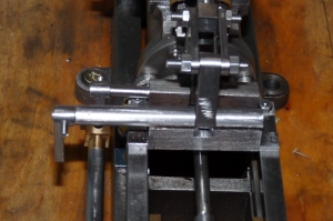
I had no real option to deviate from the style of the first bridge component as the lever shaft extends quite a way from the bridge, even in the original design.
You can see this in the picture here.

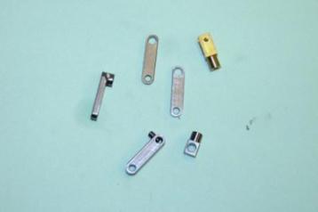
My re-design of the bridge entails fabricating the piece, as the key need is to get the lever shaft properly supported along its length. So the underlying Stuart design is still there, but I took the original Stuart design, made it 1/4 inch taller to allow for the additional height of the second valve rod. The other 1/4 inch is taken care of by extending both linkages by 1/4 inch too. It’s important to keep the two levers the same length or the amount of throw at the top of the top lever will change.
Once I’d cut the blank, I drilled a pilot hole as per Stuart plan, then drilled it bigger and bigger until the top fell off! Next step was to cut a 1/4 round bar to length and drill it to take the lever shaft, following the Stuart approach. Then I brazed the drilled round bar to the bridge piece with Silver solder. Next step was to check the alignment and mark out the central slot to take the lever. I then ran a 1/4 slot drill through the bridge. All that remains is to fix the bridge to the cross head rails and fix the brass clevis to the push rod from the second eccentric and it’s done.

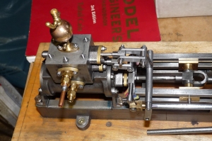
You can see here how the original Stuart design leaves the lever shaft un-supported for a significant length. I’ll probably change the original bridge piece to my design. I have seen attempts by other builders to crank the push rod towards the the bridge, I now wonder if this is why. On the Stuart design, you can’t actually crank the push rod very much as it will foul the sole plate.
Bit of luck might see this running next weekend…
-
Recent
- Functionally, it’s Done and it Works!
- Comparisons – Old and New
- Victoria Running In on 25 PSI Compressed Air.
- Form Tools Again, Comment From My Mentor…
- Finishing the Steam Cut-Off Valve
- Starting the Plumbing trip…
- Before I forget – Don’t round off the edges!
- Drilling the funny shaped piece that holds the shaft that drives the…
- Grindingly slow, but the Victoria is coming together…
- Fish Bellied Rods
- A bit of fun…
- Three hours in the workshop later…
-
Links
-
Archives
- October 2010 (6)
- September 2010 (3)
- August 2010 (7)
- July 2010 (2)
- May 2010 (3)
- April 2010 (6)
- March 2010 (1)
- November 2009 (5)
- October 2009 (1)
- September 2009 (2)
- August 2009 (1)
- June 2009 (4)
-
Categories
-
RSS
Entries RSS
Comments RSS