Functionally, it’s Done and it Works!
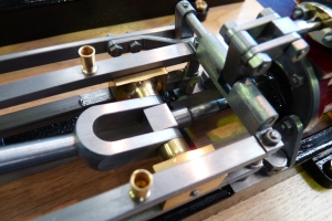
The last component went on the machine today – the lever, known as part 9 on the governor kit plan, it’s the little lever that picks up the vertical motion from the flyball governor and converts it to rotary motion to drive the steam shut off valve. I didn’t make it wholly to plan (of course). Instead of fabricating the part as per Stuart plan, I machined the lever from a solid piece of 1/4 inch square bar. I used the same profile for the lever as the plan but machining from
 solid meant that I could create a shoulder to make space for a 7BA grub screw, rather than rely on Loctite. Apologies for the image not being spin sharp, but I think it’s good enough to see the design. I’m also getting better – the grub screw is underneath the lever, out of sight, by design, not accident!
When I was in the midst of designing the gear driven governor, I got talking to a guy who had built steam engines on a commercial basis and he explained that flyball governors do not work on this scale, as the laws of physics don’t scale, which is of course perfectly true. Well, I can smugly say that this flyball governor DOES work! I have run the engine now on 60PSI compressed air and there is the odd air leak here and there, but the engine just trots along, it should go like the clappers of hell at that pressure and it doesn’t, because the flyballs do rise and do cut-off the air supply and the engine can’t accelerate. In other words the energy in two 5/8 inch phosphor bronze balls spinning at 200 ish rpm can be translated into enough rotary force to drive a low friction valve. I do owe the guy a beer, because his comments took me down the road of thinking about needing a very low friction cut-off valve and ultimately making one to my own design. None of the standard commercial valves I found wouldn’t have cut the mustard in this application.
So finally here she is –
Here is the engine running, regulated by the governor. The knocking noise is poor accuracy of machining by me of the inboard crankshaft bearing – if I pump it full of oil the noise goes away…One mod I did make was to fit the brass bearing blocks with Phosphor bronze shells, so I just need to make a new shell, rather than do any work on the bearing block itself. My initial intent was longevity, not ease of maintenance! There is always an upside, you just have to look for it.
http://www.youtube.com/watch?v=R6rgZ-7Y3t8
While the engine is functionally complete and working properly, there is a cabinet to be made, the various leaks to shut down before moving to live steam. I don’t intend blogging the detail of that, but will properly drop in some photo’s from time to time as the major stages are complete. I still have to make a working Meyer expansion valve, but that was always going to be the subject of a project in it’s own right. I have made some fencing posts, but at the minute I’m not minded to install a guard rail around the engine. May be I will one wet weekend, I have made a couple of the fence posts already.
One thing that did prove true was to minimise the number of colours in the paint scheme and I did spend a lot of time getting to the right scheme which has worked out in the end.
This is the second project out of the workshop, so it’s time to go for the big time – The Whittle V8 is next on the list, I was going to build David Parkers OHV 9cc V-twin, but time to be bold! The plan is to machine the crankshaft first and see how that goes. If I can produce a really good crankshaft then that will give confidence I can deal with the rest.
I’ll blog as I go, the Stuart Victoria blog has attracted over 10,000 hits to date, so it seems worth while to continue with the V8. I’ve already bought the prop and glo-plugs 🙂
Best Regards
Steve
Comparisons – Old and New
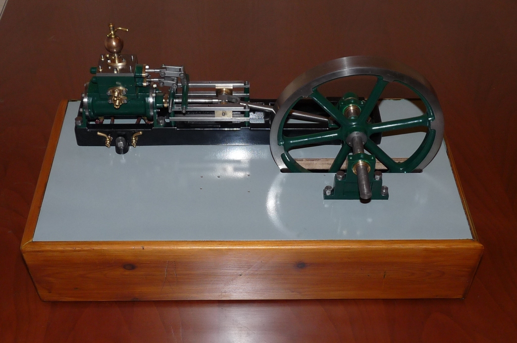
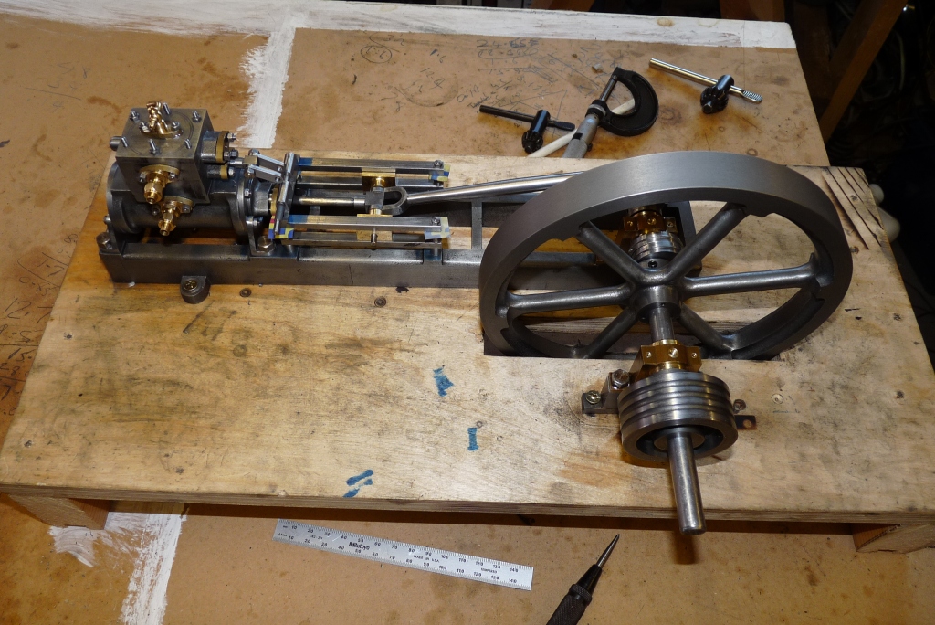
If you’ve followed this adventure from the beginning, you’ll know this project was largely inspired by an engine my Great Grandfather built around 1905, best guess. Take a look at my attempt to copy his design and compare:
That rather scales the achievement – and yes it is a working engine, not a “model”.
I also thought it would be useful to show the lathe he built to build the engine –
I guess it would have made more sense to show this little homebrew lathe in context of my lathe, but it might have got lost even against my “little” bench lathe.
This is my lathe as bought from Arceurotrade, it’s had one or two mods since I took this. It’s 10×22 class machine and the perfect size in my view for the sorts of models I’m seeking to build. It’s useful speed range is now 40 – 2600 rpm and I’ve also added a digital readout to the tailstock and got rid of the clamping bolt, which was a real nuisance when I built the Nemett. I’ve also added locking clamps to cross & top slides. I’ve installed rev counter electronics, but never implemented the display! Decided it was a pretty pointless exercise in the end. Calibrating the knob once in a while with a permanent marker works just fine.
Starting the Plumbing trip…
Started to think about how to feed the steam pipes through the base and came up with this design:
The principle is that the flange is dressed to look like a steam flange by adding three 10BA hex head screws, the assembly fits through a 1/4 inch hole in the base plate and a 1/4 x 40tpi nut pulls it tight. A standard 1/4 x 40tpi steam connector can then be used to hook up to the external pipework. It’s a pretty simple turning job.
The sequence I used was to turn the workpiece to the finished diameter of the flange. Then turn the remainder down to 1/4 inch, thread and drill the through hole and cut the taper. Once I had two completed to this stage, I swapped chucks for the independent 4 Jaw centred with piece with a clock and then finished off. The top is simply drilled 5/32nd with the intention of soldering the steam pipe in place.
a
a
a
a
a
a
a
a
Here the connector is transferred to the rotary table to drill the holes to tapping size to take the three 10BA screws, and on the right, the set of components completed. I won’t bore you with the details of how to drill a hole and make a nut from brass hexagon bar…
The next instalment is finishing off the steam cut-off valve.
Grindingly slow, but the Victoria is coming together…
Shot from the front – a lot of “fitting” going on which is slow work. There is a spacer behind the large bevel wheel on the crankshaft which needed thinning to ensure a good mesh between the two wheels, got it right after two cuts, but lots of ops to get it done, on the lathe (setting up the backstop I used for turning the eccentric straps) and making a long handled 2mm allen key to get the screws in and out of the flywheel that secure the bevel wheel.
Having machined, fitted, painted, woodworked and fitted, I’m getting quickly towards the plumbing part. Never ends this steam engine building. I reckon my design changes to the basic Victoria have tripled the elapsed build time.
Nothing particular to remark on from this side, I deliberately laid the engine out so everything was “happening” from the front, as ultimately it’s a display piece.
I’ve tried running it a couple of times today, but the timing keeps slipping, so I’ve used Loctite in the offending places as advised by Stuart. On the initial run a long while back, I had flats on the shafts so the levers wouldn’t slip. I’ve since remade the shafts, without the flats and hence the slip.
Actually, there is a comment – this side of the base has a Roman flute applied, whereas the front is plain. That’s me just fooling around with my router to see which looks best for the final version of the base.
Fish Bellied Rods
I’d originally planned to ” fishbelly” (a new Nerb?) the slide valve pushrods, then changed my mind and today did it anyway!
I stripped down the push rod assemblies and mounted in the lathe. If you wind back through the blog far enough you will find I had centre drilled the rods for the purpose of creating the fishtails and I’d made a little fixture for holding the rod at the chuck end of things. The short rod I can almost get half the rod before I run out of travel, the longer rod I’m about 1/2 inch short. For the longer rod then, I end up with a flat in the middle. For both rods the shaping is finished with coarse emery tape with the lathe at full speed, then cleaning up with a 400 grade emery and brasso, followed by 800 wet and dry and brasso etc.
Here is the rod re-assembled and with the eccentric strap cleaned up. Looks much better.
As an aside, you will have noticed that I’ve now acquired a quick change tool post (QCTP to those that know about these things). To be honest not sure of the value it adds, thought it is handy for fine tuning tool heights. It isn’t as quick as spinning round a four post tool holder in my view.
Victoria Begins to Emerge…
Scrubbing up nicely! The wooden base is a prototype for me to check sizes and allow me to sort out the plumbing. I’m planning on the steam inlet and exhaust terminating in 1/4 x 40 tpi connectors on the back panel of the base.
Spot the Oops…Looks like I need to go back a few steps!
Paint Job -Stuart Victoria
The painted components kept safe in a wooden box. Really important now to protect the components from damage. I’ll leave them alone for the paint to harden off properly for a week or so. This will ensure best resilience as the engine is assembled. The sole plate failed the quality test (added a grey thumb print to the front side which wouldn’t polish out…) so it’s now drying off. Hopefully, final coat of black gloss.
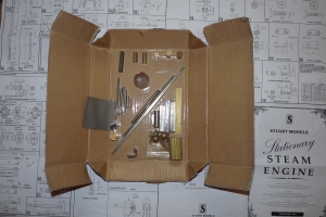
As a reminder the journey started here, back in December 2008…
The we moved into governor territory –
The odd thing is, having finished the governor assembly, I still have most of the parts left over!
Now planning to have the whole thing ready to steam before the end of October, this would leave plenty of time to do plumbing and sort steam generation in time for the christmas holidays.
Painting, Masking, Painting
Since the weather has turned dry and warm, I decided to paint the principal components of the engine. After much mental anguish, this is the scheme.
Sole plate is black. Cylinder, steam chest, flywheel, all bearing block and stanchions to be green. Spray painting is the order of the day, which means lots of careful masking out. Painstaking attention to the masking out is key to a good spray job.
I used Polykote grey primer, which is a cellulose based paint and that went on a real treat. For the sole plate, I used Polykote gloss black and for the “green” bits a can of Halfords Vauxhall Pine Green. They had quite a few different flat gloss colours (ie not Pearlescent or Metallic) that were close to “Stuart Green”. This paint is acryllic and doesn’t go on as well but dries very quickly in the warm weather. It will also stand wet and dry to get rid of any excrescences.
The sole plate had some vertical scores which remained very evident in primer, so I used some cellulose stopper to fill them and one or two other dinks. Cellulose stopper is now known as “fine surface filler” and it’s probably not a good idea to use it on the acryllic finish.
The marks can be seen in this video clip: http://www.youtube.com/watch?v=Kzk8EwN7-34
In close up, you can see I’ve rubbed down the raw casting to get a smooth surface, but the marks are quite deep.
It’s actually quite difficult to decide what to paint and what not. Got quite a lot done and the flywheel looks pretty smart even though it needs tidying up. I’m not going to touch it now for a week to ensure the paint is hard enough to stand being worked.
I’ve added both “rubbing compound” and T-Cut to the paint box so I’ve a range of materials to use to get to a good polished finish.
When I started building the engine, I really didn’t realise how much woodworking and painting is needed to finish. The paint job and the woodwork has to be to a high standard or else all the design and manufacture effort that’s gone in to produce the engine will be undermined.
One thing to thing about is the thickness of the final paint job in relation to the scale of the engine – it will interfere with the fit of some components on assembly if care is not taken. (Attention to masking out again).
Definitely going to build an IC engine next ( Whittle V8? ) !!! No woodwork or painting !
Adding the Drain Cocks
These are the tales of Bloggin’ the Blog…
One of the ommissions with the Stuart Victoria castings set, is that the plan makes no reference to the installation of drain cocks. The cocks can’t be fitted to the cylinder conventionally, since the bottom of the cylinder is obscured by the mounting flanges and on the piston rod end, access would be prevented because of the valve gear arrangement.
+
+
+
+
+
+
+
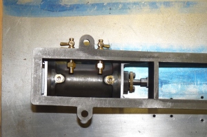
As an example the in-board drain cock would be buried under all this mechanism!
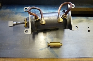
So the answer is to make connections to the bottom of the cylinder, then with a bit of plumbing, bring the drain cocks out to the side of the sole plate, well that’s how I did it.
+
+
+
+
+
+
+
+
The Victoria cylinder is a shared casting with the Stuart Beam. For the Beam engine, the two lands in the casting are drilled and tapped to take the steam cocks directly. This does’t work for the Victoria as the cocks would be inaccessible. So I’m drilling and tapping them to take a couple of connectors to take a 5/32 copper pipe. I would strongly recommend making this the next operation after facing the steam ports, not the very last as I did. A mistake at this point would cost a lot of re-work.
+
+
+
+
+
+
+
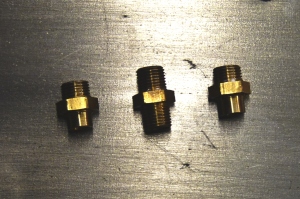
The connector in the centre is a standard 1/4 * 40 tpi fitting. I’ve converted two of these to the design left and right of centre. One end I’ve simply shortened to 4.5mm. The other end, I’ve turned off the threads, shortened to 4.5mm and drilled out to 5/32 and about 8mm deep so I can silver solder in the copper drain pipe.
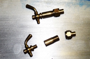
Next, it’s necessary to bring the pipe to a drain cock. I decided to make a brass connector (between the cock and the union fitting in the picture) from 1/4 brass rod that will be a press fit through the sole plate. The connector has to be made in a specific sequence and I also used a collet chuck to hold the workpiece. Step 1. is to face and thread the bar 1/4 * 40tpi. Then I used a centre drill to create the taper socket for the cone nipple. The part off the piece 16mm long and clamp the piece the otherway round in the collet chuck. Now face off, drill 3.4mm and tap 5/32 to take the drain cock.
+
Next, need to drill the sole plate to take the brass connectors:
+
+
+
+
+
+
+
+
+
+
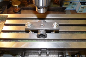
To get everything square, I mounted the sole plate on an angle plate on the mill bed.
+
+
+
+
+
+
+
Finally, all installed less the pipe work.
The the pipework. Not particularly pleased with the finished pipes, but they are functionally OK. I made a mandrel for bending the pipe and kept the pipe annealed during the bending process, but still couldn’t get a good finish. One mistake was squeezing a flat on the pipe whilst soldering on a nipple. Oops.
Stuart Victoria – A Trial Fit of the Initial Components
Time is a precious and I’ve made some to move the build of my Victoria on a bit.

This is my Victoria in its first trial fit condition. You will notice a number of differences to the standard Victoria build (and there are more to come).
The key differences are:
- The Steam Chest is configured to support the implementation of a Meyer Expansion valve arrangement;
- The Steam inlet is on the side of the upper part of the steam chest;
- The top of the steam chest is configured for the implementation of a “Shapely Lady” lubricator;
- The flywheel is being implemented to be “sub-grade”;
- Looking through te spokes of the flywheel the twin eccentrics can be seen;
- This configuration of the Victoria rules out the use of Stuart’s outboard bearing mount; and
- In the foreground are a pair of bevel gears which will drive the Stuart governor.

The modified bearing blck mounting is made by milling a piece of BMS flat to an “I” section, then silver soldering a second piece of BMS to one end to create a base. The top section of the “I” section is then tapped and drilled to take the bearing block.
Next task is to complete the valve drive from the eccentric. Again this won’t be to the Stuart design – the plan is to use fishtail rods screwed into the eccentric straps and connected via a clevis at the valve end of things. I think this will look pretty smart, but importantly reduce the space needed to accomodate the two eccentrics. Pictures to follow as soon as workshop time permits…
-
Recent
- Functionally, it’s Done and it Works!
- Comparisons – Old and New
- Victoria Running In on 25 PSI Compressed Air.
- Form Tools Again, Comment From My Mentor…
- Finishing the Steam Cut-Off Valve
- Starting the Plumbing trip…
- Before I forget – Don’t round off the edges!
- Drilling the funny shaped piece that holds the shaft that drives the…
- Grindingly slow, but the Victoria is coming together…
- Fish Bellied Rods
- A bit of fun…
- Three hours in the workshop later…
-
Links
-
Archives
- October 2010 (6)
- September 2010 (3)
- August 2010 (7)
- July 2010 (2)
- May 2010 (3)
- April 2010 (6)
- March 2010 (1)
- November 2009 (5)
- October 2009 (1)
- September 2009 (2)
- August 2009 (1)
- June 2009 (4)
-
Categories
-
RSS
Entries RSS
Comments RSS


