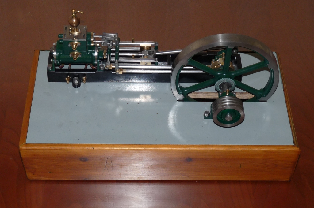
Functionally, it’s Done and it Works!
The last component went on the machine today – the lever, known as part 9 on the governor kit plan, it’s the little lever that picks up the vertical motion from the flyball governor and converts it to rotary motion to drive the steam shut off valve. I didn’t make it wholly to plan (of course). Instead of fabricating the part as per Stuart plan, I machined the lever from a solid piece of 1/4 inch square bar. I used the same profile for the lever as the plan but machining from
 solid meant that I could create a shoulder to make space for a 7BA grub screw, rather than rely on Loctite. Apologies for the image not being spin sharp, but I think it’s good enough to see the design. I’m also getting better – the grub screw is underneath the lever, out of sight, by design, not accident!
When I was in the midst of designing the gear driven governor, I got talking to a guy who had built steam engines on a commercial basis and he explained that flyball governors do not work on this scale, as the laws of physics don’t scale, which is of course perfectly true. Well, I can smugly say that this flyball governor DOES work! I have run the engine now on 60PSI compressed air and there is the odd air leak here and there, but the engine just trots along, it should go like the clappers of hell at that pressure and it doesn’t, because the flyballs do rise and do cut-off the air supply and the engine can’t accelerate. In other words the energy in two 5/8 inch phosphor bronze balls spinning at 200 ish rpm can be translated into enough rotary force to drive a low friction valve. I do owe the guy a beer, because his comments took me down the road of thinking about needing a very low friction cut-off valve and ultimately making one to my own design. None of the standard commercial valves I found wouldn’t have cut the mustard in this application.
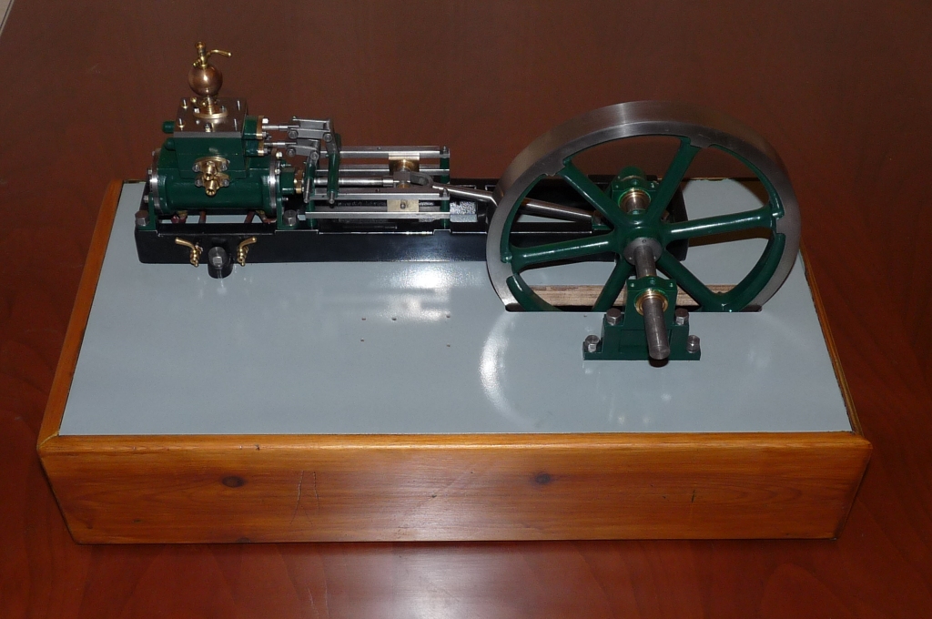
So finally here she is –
Here is the engine running, regulated by the governor. The knocking noise is poor accuracy of machining by me of the inboard crankshaft bearing – if I pump it full of oil the noise goes away…One mod I did make was to fit the brass bearing blocks with Phosphor bronze shells, so I just need to make a new shell, rather than do any work on the bearing block itself. My initial intent was longevity, not ease of maintenance! There is always an upside, you just have to look for it.
http://www.youtube.com/watch?v=R6rgZ-7Y3t8
While the engine is functionally complete and working properly, there is a cabinet to be made, the various leaks to shut down before moving to live steam. I don’t intend blogging the detail of that, but will properly drop in some photo’s from time to time as the major stages are complete. I still have to make a working Meyer expansion valve, but that was always going to be the subject of a project in it’s own right. I have made some fencing posts, but at the minute I’m not minded to install a guard rail around the engine. May be I will one wet weekend, I have made a couple of the fence posts already.
One thing that did prove true was to minimise the number of colours in the paint scheme and I did spend a lot of time getting to the right scheme which has worked out in the end.
This is the second project out of the workshop, so it’s time to go for the big time – The Whittle V8 is next on the list, I was going to build David Parkers OHV 9cc V-twin, but time to be bold! The plan is to machine the crankshaft first and see how that goes. If I can produce a really good crankshaft then that will give confidence I can deal with the rest.
I’ll blog as I go, the Stuart Victoria blog has attracted over 10,000 hits to date, so it seems worth while to continue with the V8. I’ve already bought the prop and glo-plugs 🙂
Best Regards
Steve
Comparisons – Old and New
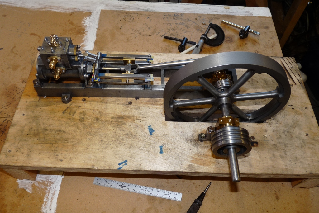
If you’ve followed this adventure from the beginning, you’ll know this project was largely inspired by an engine my Great Grandfather built around 1905, best guess. Take a look at my attempt to copy his design and compare:
That rather scales the achievement – and yes it is a working engine, not a “model”.
I also thought it would be useful to show the lathe he built to build the engine –
I guess it would have made more sense to show this little homebrew lathe in context of my lathe, but it might have got lost even against my “little” bench lathe.
This is my lathe as bought from Arceurotrade, it’s had one or two mods since I took this. It’s 10×22 class machine and the perfect size in my view for the sorts of models I’m seeking to build. It’s useful speed range is now 40 – 2600 rpm and I’ve also added a digital readout to the tailstock and got rid of the clamping bolt, which was a real nuisance when I built the Nemett. I’ve also added locking clamps to cross & top slides. I’ve installed rev counter electronics, but never implemented the display! Decided it was a pretty pointless exercise in the end. Calibrating the knob once in a while with a permanent marker works just fine.
Grindingly slow, but the Victoria is coming together…
Shot from the front – a lot of “fitting” going on which is slow work. There is a spacer behind the large bevel wheel on the crankshaft which needed thinning to ensure a good mesh between the two wheels, got it right after two cuts, but lots of ops to get it done, on the lathe (setting up the backstop I used for turning the eccentric straps) and making a long handled 2mm allen key to get the screws in and out of the flywheel that secure the bevel wheel.
Having machined, fitted, painted, woodworked and fitted, I’m getting quickly towards the plumbing part. Never ends this steam engine building. I reckon my design changes to the basic Victoria have tripled the elapsed build time.
Nothing particular to remark on from this side, I deliberately laid the engine out so everything was “happening” from the front, as ultimately it’s a display piece.
I’ve tried running it a couple of times today, but the timing keeps slipping, so I’ve used Loctite in the offending places as advised by Stuart. On the initial run a long while back, I had flats on the shafts so the levers wouldn’t slip. I’ve since remade the shafts, without the flats and hence the slip.
Actually, there is a comment – this side of the base has a Roman flute applied, whereas the front is plain. That’s me just fooling around with my router to see which looks best for the final version of the base.
Three hours in the workshop later…
You can see I’ve fixed the mis-assembly of the steam chest. The steam inlet height is matched to the height of the governor.
Three hours more in the workshop and I’m now at the stage of fitting the slide valve push rods. My method is simply to start with the cylinder and work forward, trial fit a part, fettle and finally fit. The rods themselves need quite some work as the raw material has a sprial pattern which light rubbing down won’t sort. I think I’ll probably put the rods back on the machine and give them a definite fishtail. The upside is that the material does actually polish up well.
A strange thing, but the crankshaft which I finished to size on assembly, is now too long by around 4mm. Must have grown during the humid summer months! I need to work out what’s happened BEFORE I shorten it or I may end up needing a new crankshaft.
A lot of work yet to do.
Victoria Begins to Emerge…
Scrubbing up nicely! The wooden base is a prototype for me to check sizes and allow me to sort out the plumbing. I’m planning on the steam inlet and exhaust terminating in 1/4 x 40 tpi connectors on the back panel of the base.
Spot the Oops…Looks like I need to go back a few steps!
Back to the Bevel Gears for the Stuart Victoria
So, having completed the eccentric straps, I’m back to making the bevel gears I need. I reviewed the design again and discovered that the dividing plate on my rotary table doesn’t support cutting a 26 tooth gear, but will support 27 teeth. The impact on the gear ratio is immaterial and makes a slight change to the pitch cone angles.
I haven’t done this before and the starting point is a 40DP involute cutter. So – I’ve made an arbor to hold the cutter:

Set of Components for the Arbor
Here is the Arbor and cutter mounted in the mill:

Cutter set up in the mill
The Mill is a round column Warco Minor which has given great service so far, but it hasn’t yet cut any bevel gears!
Next job is to make a gear blank so I have something to cut, so I cut a blank suitable for the number of teeth that is compatible with a No.3 cutter I have. Once I’ve got the Parallel Depth method working for me, then I can consider procuring the specific cutters for the task.

Turning a Gear Blank

Finished Practice Blank
Next step is to set up the Rotary Table on the Mill so that I can practice cutting some teeth on the blank…
Bevel Gears for the Stuart Victoria – Parallel Depth Method
From a previous blog you will remember that I’ve decided to replace the spring drive belt and pulley system used to drive the flyball governor, with a gear driven shaft, which reflects my Great grandfathers view on the subject.
Standard bevel gears are typically beyond the average home workshop, because of the complex geometry. I discovered a solution to this problem “The Parallel Depth Method”. This approach allows bevel gears to be cut on a milling machine and whilst the geometry is simpler, the resulting gears are more than adequate for the job at hand. The method was derived during the 1914-18 war in order to allow bevel gears to be produced on simpler machines with lesser skilled people.
In Ivan Law’s book “Gears and Gear Cutting” Mr Law lays out the method clearly with worked examples of the design formulae. I’ve taken these formulae and constructed the following excel worksheet:
http://www.btinternet.com/~steve.withnell/lathe/gears.xls
The parameters as loaded are looking just about right for my build (an artist would probably say “interpretation”) of the Stuart Victoria.
No gears cut yet, but once done, I will of course upload pictures and my experiences. Not having done this before, no doubt there will be an element of learning (ie scrap)!
Thinking About Bevel Gears
To implement a shaft drive on the Stuart Victoria to drive the flyball governor, I need two sets of bevel gears. Off the shelf these would cost in the region of £100. Research shows it possible to cut bevel gears in the homeworkshop using he “Parallel Depth Method”, which uses a standard mill.
Ivan Law’s book gives a detailed description, so I’m following his text on the design of the gears.
-
Recent
- Functionally, it’s Done and it Works!
- Comparisons – Old and New
- Victoria Running In on 25 PSI Compressed Air.
- Form Tools Again, Comment From My Mentor…
- Finishing the Steam Cut-Off Valve
- Starting the Plumbing trip…
- Before I forget – Don’t round off the edges!
- Drilling the funny shaped piece that holds the shaft that drives the…
- Grindingly slow, but the Victoria is coming together…
- Fish Bellied Rods
- A bit of fun…
- Three hours in the workshop later…
-
Links
-
Archives
- October 2010 (6)
- September 2010 (3)
- August 2010 (7)
- July 2010 (2)
- May 2010 (3)
- April 2010 (6)
- March 2010 (1)
- November 2009 (5)
- October 2009 (1)
- September 2009 (2)
- August 2009 (1)
- June 2009 (4)
-
Categories
-
RSS
Entries RSS
Comments RSS


