A bit of fun…
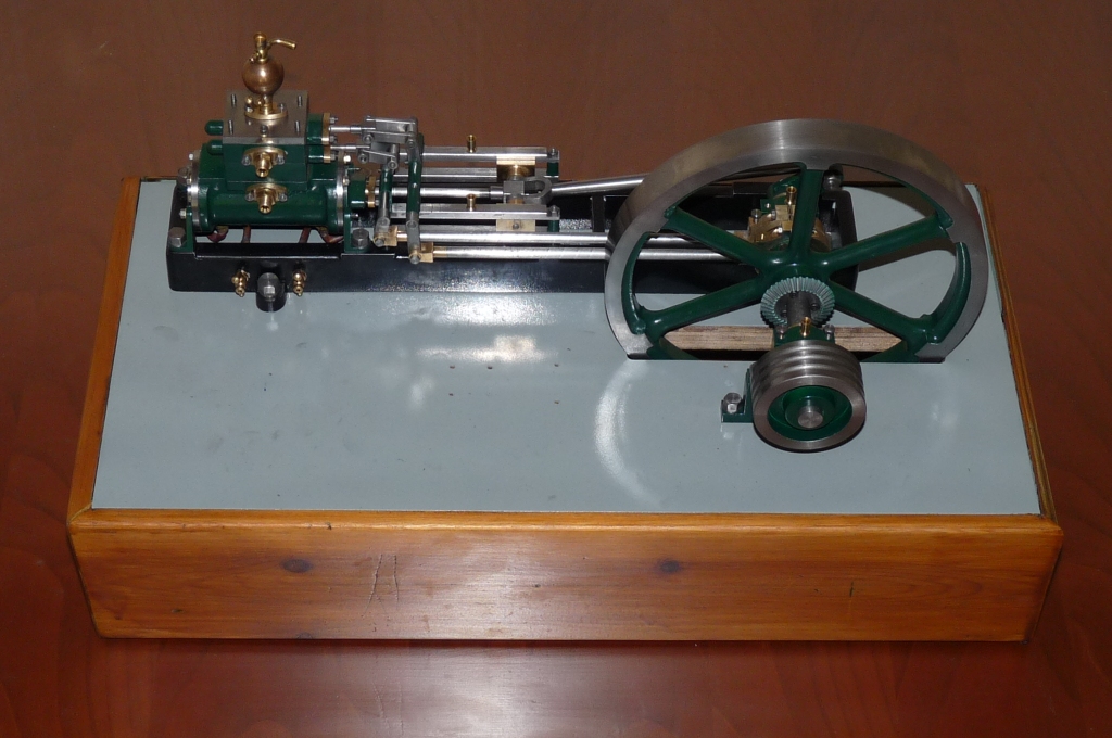
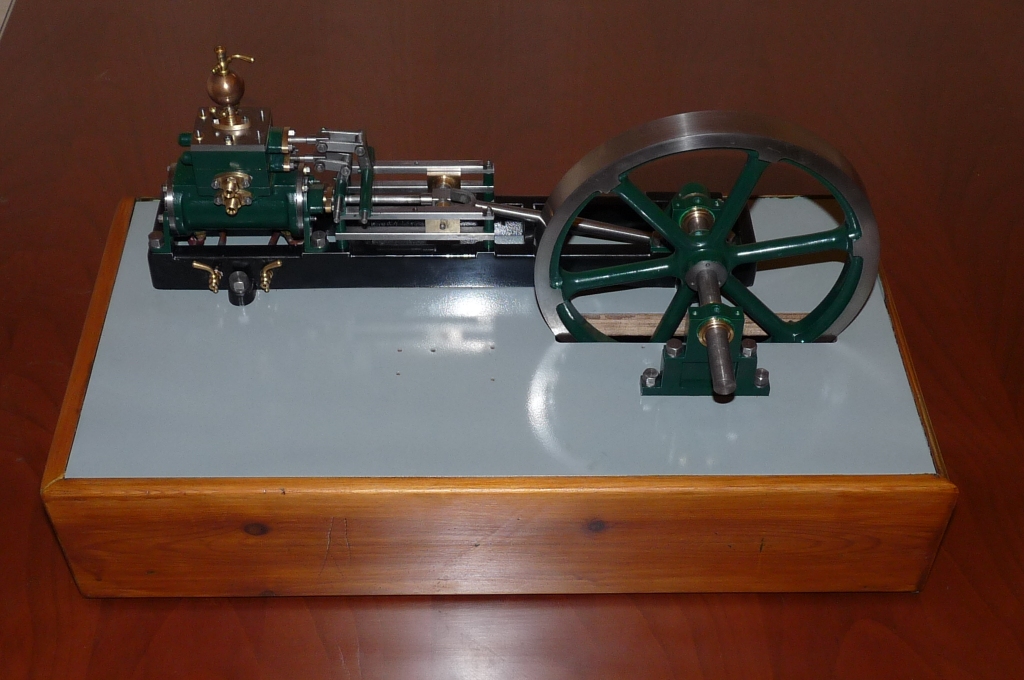
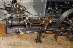
I’ve decide to add some fencing to the engine stand to give some perspective. Great Grandfathers engine does this quite effectively, so simple to follow the theme.
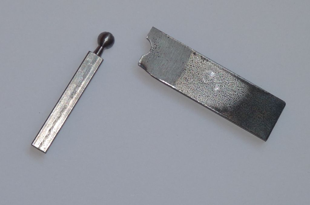
First off, I cut four lengths of 1/4 square bar to 50mm length. Then mounting one in the lathe started to think about how to shape a ball end to the post. After a bit of messing about with a file, I remembered a UseNet post from Workshop Master Stevenson. The method is to take a piece of gauge plate and drill a hole in it the diameter of the ball you want. Countersink until you get a sharp edge then saw through the hole. Grind to appropriate profile, harden, temper, grind a bit more and there you go:
I didn’t have any gauge plate 😦 so I used a piece of EN3B flat. As you can see, it works a treat. The profile isn’t right yet as the form tool (which is what this is) is flat topped, which isn’t right, I don’t think, so abit more fiddling with the grinder and this should be great. At least it saves buying or making a ball turner. Thanks JS.
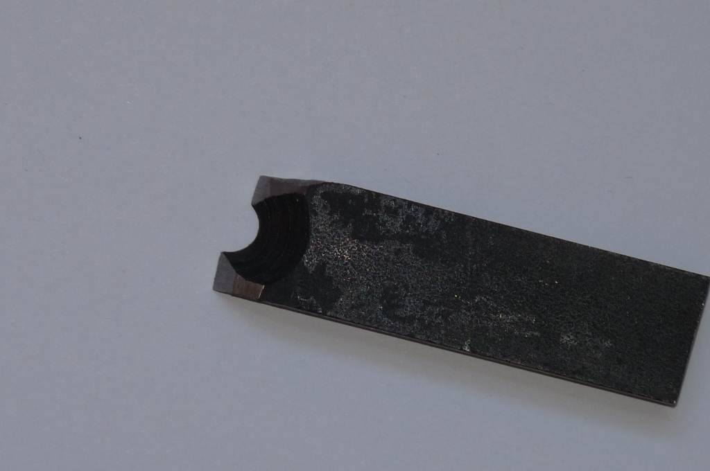
Here you can see how I’ve used my biggest countersink to create a cutting edge in the diameter of the hole. It’s not profiled correctly yet, but did produce a decent result first off. The underside is all a bit scaly from the heat treatment.
Someone will post to let me know that you can buy fence posts from the model shop. If I had done that, I wouldn’t have learned how to make a form tool – and that’s why I make most of my own stuff. I could have bought the bevel gears too, or gone the whole hog and bought a ready to run engine from Stuart but I would have been a lot poorer in cash, knowledge and skills if I’d done so!
Three hours in the workshop later…
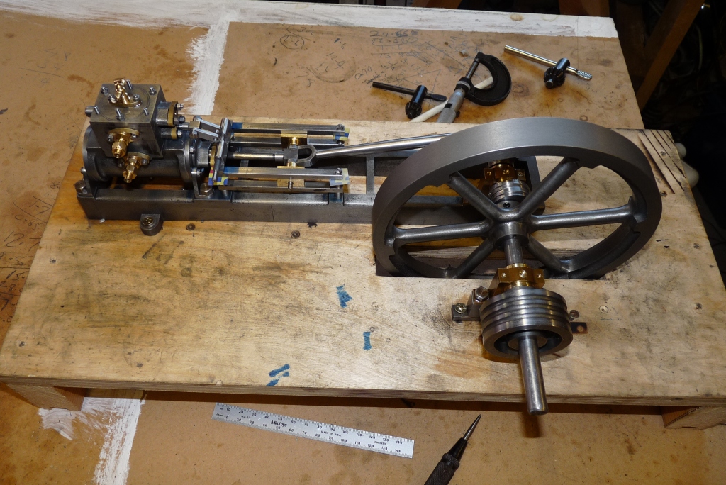
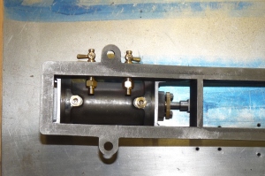
You can see I’ve fixed the mis-assembly of the steam chest. The steam inlet height is matched to the height of the governor.
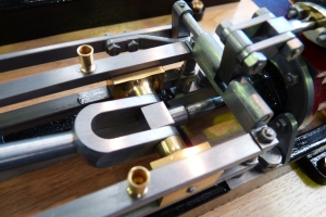
Three hours more in the workshop and I’m now at the stage of fitting the slide valve push rods. My method is simply to start with the cylinder and work forward, trial fit a part, fettle and finally fit. The rods themselves need quite some work as the raw material has a sprial pattern which light rubbing down won’t sort. I think I’ll probably put the rods back on the machine and give them a definite fishtail. The upside is that the material does actually polish up well.
A strange thing, but the crankshaft which I finished to size on assembly, is now too long by around 4mm. Must have grown during the humid summer months! I need to work out what’s happened BEFORE I shorten it or I may end up needing a new crankshaft.
A lot of work yet to do.
Victoria Begins to Emerge…
Scrubbing up nicely! The wooden base is a prototype for me to check sizes and allow me to sort out the plumbing. I’m planning on the steam inlet and exhaust terminating in 1/4 x 40 tpi connectors on the back panel of the base.
Spot the Oops…Looks like I need to go back a few steps!
Paint Job -Stuart Victoria
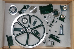
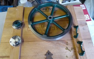
The painted components kept safe in a wooden box. Really important now to protect the components from damage. I’ll leave them alone for the paint to harden off properly for a week or so. This will ensure best resilience as the engine is assembled. The sole plate failed the quality test (added a grey thumb print to the front side which wouldn’t polish out…) so it’s now drying off. Hopefully, final coat of black gloss.
As a reminder the journey started here, back in December 2008…
The we moved into governor territory –
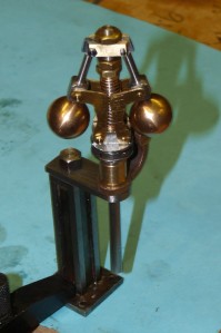
The odd thing is, having finished the governor assembly, I still have most of the parts left over!
Now planning to have the whole thing ready to steam before the end of October, this would leave plenty of time to do plumbing and sort steam generation in time for the christmas holidays.
Wishee Washee’s Laundry
Or at least that’s what it looks like…Painting and more painting…
 Finally decided whats getting painted and what’s not. Well I’ve decided what is definitely getting painted. There might be one or two odds and ends that also get a coat of paint once the final assembly is well underway and I can get a better view of how it is all looking.
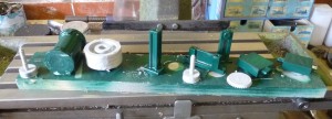
Some in grey primer, some in finish colour. The two spikey items are a stack of the spacers, just easier to do it this way. They are separated by washers so the paint can flow without issue.
The sole plate is in gloss black and should now come to a decent finish, lots of patience whilst the paint hardens off properly. The Halford’s acrylic recommends two weeks before working the top coat. Worse than gardening.
A lot to think about with this painting lark. Very important to think where the paint needs to flow when spraying. I also found that T-Cut cuts through the Halford’s acrylic like a dose of salts, so need to be very careful in its use. It seems to cut a lot faster than the CarPlan rubbing compound. Also the rubbing compounds cut through the Polykote black gloss faster than the green acrylic. So much experience needed to do this really well.
Look at the shine on those cylinder end caps – looks like a chrome plating job, but it’s just Stuart Casting scrubbing up well.
Painting, Masking, Painting
Since the weather has turned dry and warm, I decided to paint the principal components of the engine. After much mental anguish, this is the scheme.
Sole plate is black. Cylinder, steam chest, flywheel, all bearing block and stanchions to be green. Spray painting is the order of the day, which means lots of careful masking out. Painstaking attention to the masking out is key to a good spray job.
I used Polykote grey primer, which is a cellulose based paint and that went on a real treat. For the sole plate, I used Polykote gloss black and for the “green” bits a can of Halfords Vauxhall Pine Green. They had quite a few different flat gloss colours (ie not Pearlescent or Metallic) that were close to “Stuart Green”. This paint is acryllic and doesn’t go on as well but dries very quickly in the warm weather. It will also stand wet and dry to get rid of any excrescences.
The sole plate had some vertical scores which remained very evident in primer, so I used some cellulose stopper to fill them and one or two other dinks. Cellulose stopper is now known as “fine surface filler” and it’s probably not a good idea to use it on the acryllic finish.
The marks can be seen in this video clip: http://www.youtube.com/watch?v=Kzk8EwN7-34
In close up, you can see I’ve rubbed down the raw casting to get a smooth surface, but the marks are quite deep.
It’s actually quite difficult to decide what to paint and what not. Got quite a lot done and the flywheel looks pretty smart even though it needs tidying up. I’m not going to touch it now for a week to ensure the paint is hard enough to stand being worked.
I’ve added both “rubbing compound” and T-Cut to the paint box so I’ve a range of materials to use to get to a good polished finish.
When I started building the engine, I really didn’t realise how much woodworking and painting is needed to finish. The paint job and the woodwork has to be to a high standard or else all the design and manufacture effort that’s gone in to produce the engine will be undermined.
One thing to thing about is the thickness of the final paint job in relation to the scale of the engine – it will interfere with the fit of some components on assembly if care is not taken. (Attention to masking out again).
Definitely going to build an IC engine next ( Whittle V8? ) !!! No woodwork or painting !
Forgot to Mention – Drilling the drain holes!
The tale of Bloggin’ the Blog continued…
I skipped a step in the last post – The connector holes are drilled and tapped blind – NOT into the cylinder. These blind holes are then drilled through into the cylinder at 45degrees into the cylinder to get as close to the cylinder edge as possible. I used a 2mm drill, but 1.5mm would probably be better. The connector hole is c5.5mm dia. x 5.5mm deep, so it’s not possible to do more than 45 degrees.
In the picture you can see I’ve aligned the cylinder with a piece of flat material against the port face.
Adding the Drain Cocks
These are the tales of Bloggin’ the Blog…
One of the ommissions with the Stuart Victoria castings set, is that the plan makes no reference to the installation of drain cocks. The cocks can’t be fitted to the cylinder conventionally, since the bottom of the cylinder is obscured by the mounting flanges and on the piston rod end, access would be prevented because of the valve gear arrangement.
+
+
+
+
+
+
+
As an example the in-board drain cock would be buried under all this mechanism!
So the answer is to make connections to the bottom of the cylinder, then with a bit of plumbing, bring the drain cocks out to the side of the sole plate, well that’s how I did it.
+
+
+
+
+
+
+
+
The Victoria cylinder is a shared casting with the Stuart Beam. For the Beam engine, the two lands in the casting are drilled and tapped to take the steam cocks directly. This does’t work for the Victoria as the cocks would be inaccessible. So I’m drilling and tapping them to take a couple of connectors to take a 5/32 copper pipe. I would strongly recommend making this the next operation after facing the steam ports, not the very last as I did. A mistake at this point would cost a lot of re-work.
+
+
+
+
+
+
+
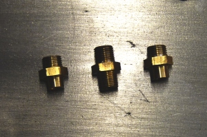
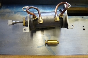
The connector in the centre is a standard 1/4 * 40 tpi fitting. I’ve converted two of these to the design left and right of centre. One end I’ve simply shortened to 4.5mm. The other end, I’ve turned off the threads, shortened to 4.5mm and drilled out to 5/32 and about 8mm deep so I can silver solder in the copper drain pipe.
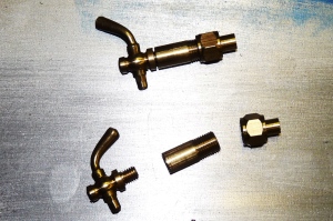
Next, it’s necessary to bring the pipe to a drain cock. I decided to make a brass connector (between the cock and the union fitting in the picture) from 1/4 brass rod that will be a press fit through the sole plate. The connector has to be made in a specific sequence and I also used a collet chuck to hold the workpiece. Step 1. is to face and thread the bar 1/4 * 40tpi. Then I used a centre drill to create the taper socket for the cone nipple. The part off the piece 16mm long and clamp the piece the otherway round in the collet chuck. Now face off, drill 3.4mm and tap 5/32 to take the drain cock.
+
Next, need to drill the sole plate to take the brass connectors:
+
+
+
+
+
+
+
+
+
+
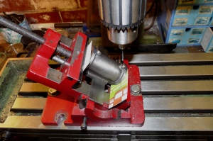
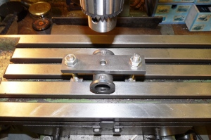
To get everything square, I mounted the sole plate on an angle plate on the mill bed.
+
+
+
+
+
+
+
Finally, all installed less the pipe work.
The the pipework. Not particularly pleased with the finished pipes, but they are functionally OK. I made a mandrel for bending the pipe and kept the pipe annealed during the bending process, but still couldn’t get a good finish. One mistake was squeezing a flat on the pipe whilst soldering on a nipple. Oops.
Meyer Expansion Valve Arrangement – Lucky Find!
I’ve been spending some quiet time looking at Eric Whittle’s V8, of which there is a wonderful video clip on Youtube:
http://www.youtube.com/watch?v=B-SNDErd1IM
I’d already built Nemett’s 15cc OHC engine before building Victoria, and am planning to build another Internal Combustion engine. I discovered that Mr. Whittle had published an earlier article in Volume 15 of Engineering in Miniature of a version of the “Cirrus”, a 4 cylinder in line OHV aero engine, upon which the V8 was based. By good luck, the large majority of the construction article is completed in volume 15, but not quite, as the article starts in Issue 2.
Having a look at issue 1, there is an article under the non-descript heading of “Odd Castings to a Finished Engine” by Don Unwin. Mr. Unwin is clearly a master craftsman. From his box of odd castings, he describes the build of a horizontal engine, complete with a working Meyer Expansion Valve. This includes the manual adjustment of the valve.
He describes in the article that the cut-off is variable between 75% right down to 15% and he also confirms the timing arrangements. The expansion valve eccentric he fixes at 180 degrees opposite the crankpin, then the primary valve +/- 115 degrees depending on the direction of rotation required.
Mr Unwin also includes reference to a number of design references of the period:
Elements of Machine Design, by WC Unwin (no relation!) pub. 1883
Bailey’s Useful Inventions for Engineers pub. 1900
The article is not a cut by cut build, but does provide a lot a detail around the Meyer arrangement.
-
Recent
- Functionally, it’s Done and it Works!
- Comparisons – Old and New
- Victoria Running In on 25 PSI Compressed Air.
- Form Tools Again, Comment From My Mentor…
- Finishing the Steam Cut-Off Valve
- Starting the Plumbing trip…
- Before I forget – Don’t round off the edges!
- Drilling the funny shaped piece that holds the shaft that drives the…
- Grindingly slow, but the Victoria is coming together…
- Fish Bellied Rods
- A bit of fun…
- Three hours in the workshop later…
-
Links
-
Archives
- October 2010 (6)
- September 2010 (3)
- August 2010 (7)
- July 2010 (2)
- May 2010 (3)
- April 2010 (6)
- March 2010 (1)
- November 2009 (5)
- October 2009 (1)
- September 2009 (2)
- August 2009 (1)
- June 2009 (4)
-
Categories
-
RSS
Entries RSS
Comments RSS
